Parallel Execution
The parallel execution model of Doris is a Pipeline execution model, primarily inspired by the implementation described in the Hyper paper. The Pipeline execution model fully leverages the computational power of multi-core CPUs while limiting the number of query threads in Doris, addressing the issue of thread explosion during execution. For details on its design, implementation, and effectiveness, refer to [DSIP-027](DSIP-027: Support Pipeline Exec Engine - DORIS - Apache Software Foundation) and [DSIP-035](DSIP-035: PipelineX Execution Engine - DORIS - Apache Software Foundation).
Starting from Doris 3.0, the Pipeline execution model has completely replaced the original Volcano model. Based on the Pipeline execution model, Doris supports the parallel processing of Query, DDL, and DML statements.
Physical Plan
To better understand the Pipeline execution model, it is first necessary to introduce two important concepts in the physical query plan: PlanFragment and PlanNode. We will use the following SQL statement as an example:
SELECT k1, SUM(v1) FROM A,B WHERE A.k2 = B.k2 GROUP BY k1 ORDER BY SUM(v1);
FE will first translate it into the following logical plan, each node represents a PlanNode. The detail meaning of each node type can be found in the introduction of physical plan.
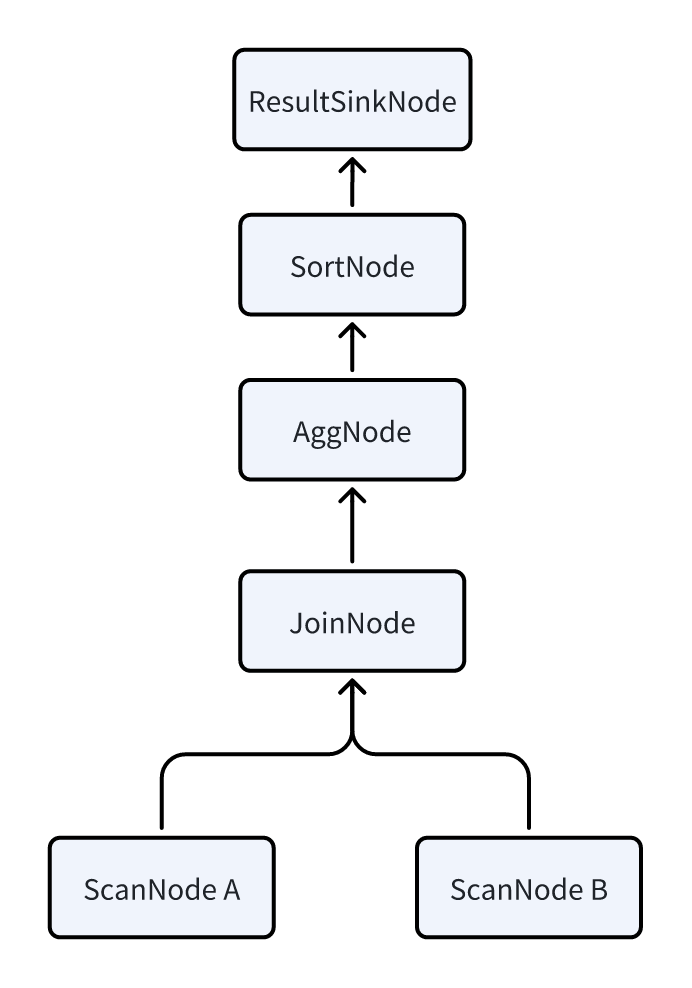
Since Doris is built on an MPP architecture, each query aims to involve all BEs in parallel execution as much as possible to reduce query latency. Therefore, the logical plan must be transformed into a physical plan. The transformation essentially involves inserting DataSink and ExchangeNode into the logical plan. These two nodes facilitate the shuffling of data across multiple BEs.
After the transformation, each PlanFragment corresponds to a portion of the PlanNode and can be sent as an independent task to a BE. Each BE processes the PlanNode contained within the PlanFragment and then uses the DataSink and ExchangeNode operators to shuffle data to other BEs for subsequent computation.
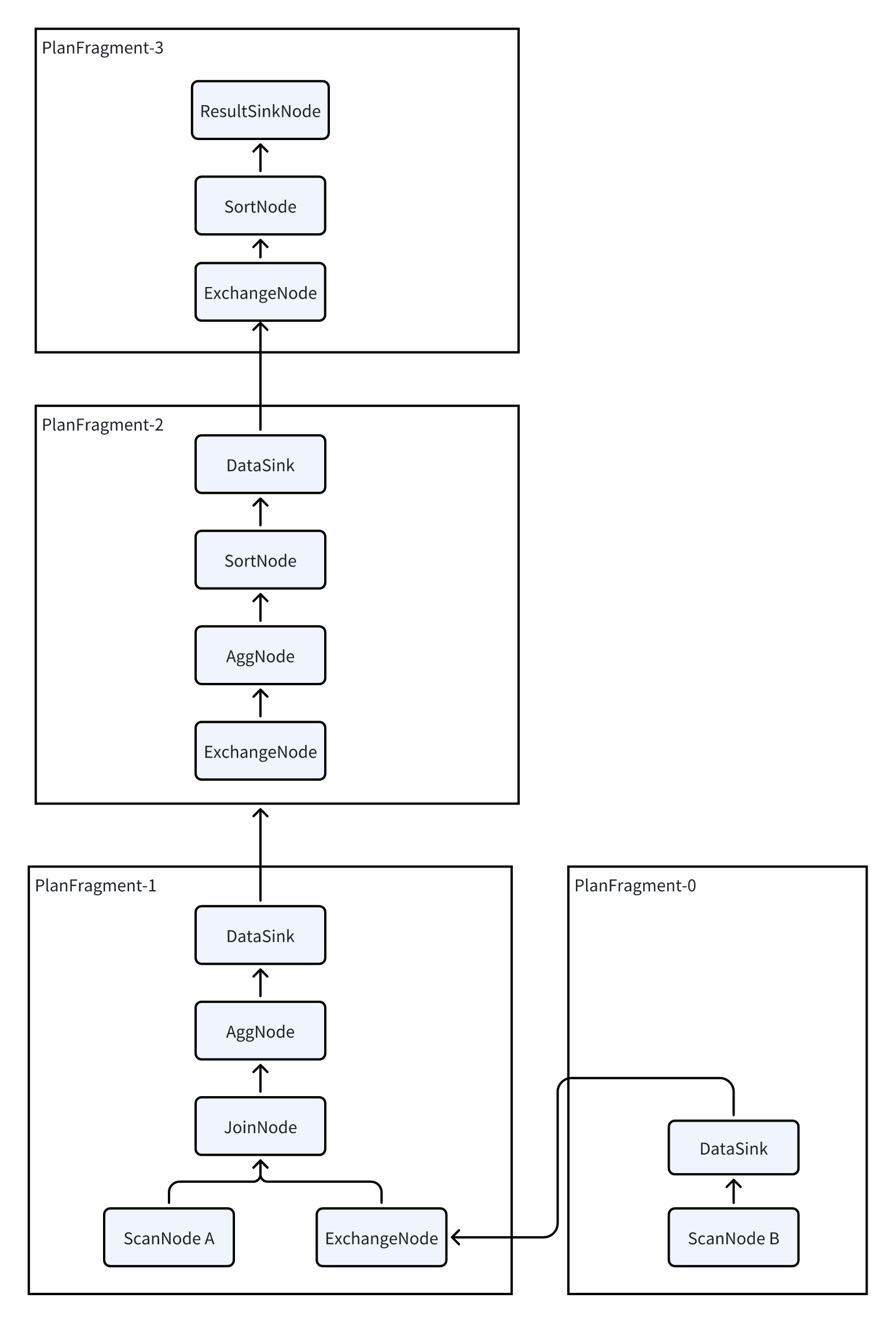
Doris's plan is divided into three layers:
-
PLAN: The execution plan. A SQL statement is translated by the query planner into an execution plan, which is then provided to the execution engine for execution.
-
FRAGMENT: Since Doris is a distributed execution engine, a complete execution plan is divided into multiple single-machine execution fragments. A FRAGMENT represents a complete single-machine execution fragment. Multiple fragments combine to form a complete PLAN.
-
PLAN NODE: Operators, which are the smallest units of the execution plan. A FRAGMENT consists of multiple operators, each responsible for a specific execution logic, such as aggregation or join operations.
Pipeline Execution
A PlanFragment is the smallest unit of a task sent by the FE to the BE for execution. A BE may receive multiple different PlanFragments for the same query, and each PlanFragment is processed independently. Upon receiving a PlanFragment, the BE splits it into multiple Pipelines and then starts multiple PipelineTasks to achieve parallel execution, thereby improving query efficiency.
Pipeline
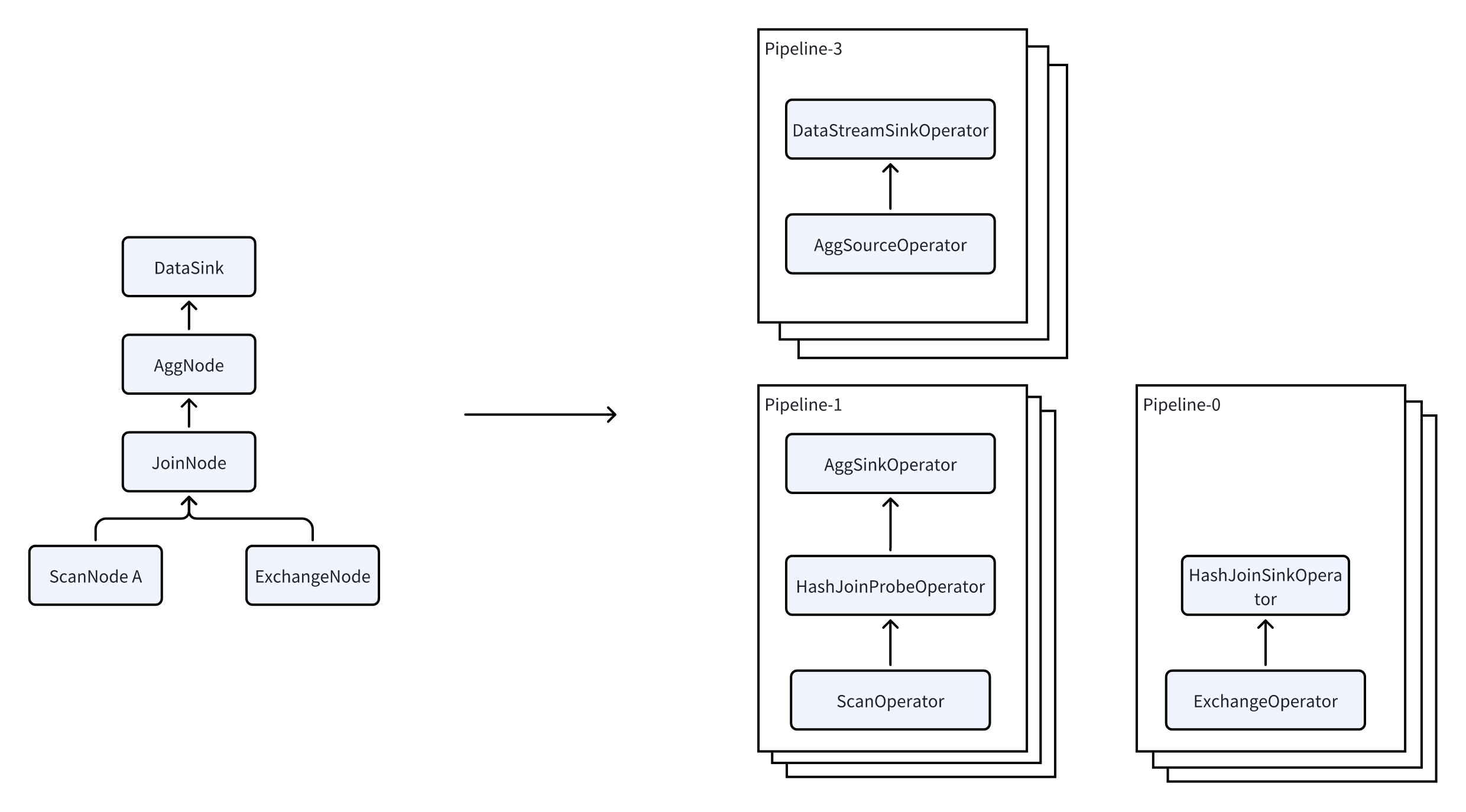
Pipeline consists of a SourceOperator, a SinkOperator, and several intermediate operators. The SourceOperator represents reading data from an external source, which can be a table (e.g., OlapTable) or a buffer (e.g., Exchange). The SinkOperator represents the data output, which can either be shuffled to other nodes over the network (e.g., DataStreamSinkOperator) or output to a hash table (e.g., aggregation operators, join build hash tables, etc.).

Multiple Pipelines are actually interdependent. Take the JoinNode as an example—it is split into two Pipelines. Pipeline-0 reads data from Exchange to build the hash table, while Pipeline-1 reads data from the table to perform the probe operation. These two Pipelines are connected by a dependency relationship, meaning Pipeline-1 can only execute after Pipeline-0 has completed. This dependency relationship is referred to as a Dependency. Once Pipeline-0 finishes execution, it calls the set_ready method of the Dependency to notify Pipeline-1 that it is ready to execute.
PipelineTask
Pipeline is actually a logical concept; it is not an executable entity. Once a Pipeline is defined, it needs to be further instantiated into multiple PipelineTasks. The data that needs to be read is then distributed to different PipelineTasks, ultimately achieving parallel processing. The operators within the multiple PipelineTasks of the same Pipeline are identical, but they differ in their states. For example, they might read different data or build different hash tables. These differing states are referred to as LocalState.
Each PipelineTask is eventually submitted to a thread pool to be executed as an independent task. With the Dependency trigger mechanism, this approach allows better utilization of multi-core CPUs and achieves full parallelism.
Operator
In most cases, each operator in a Pipeline corresponds to a PlanNode, but there are some special operators with exceptions:
- JoinNode is split into JoinBuildOperator and JoinProbeOperator.
- AggNode is split into AggSinkOperator and AggSourceOperator.
- SortNode is split into SortSinkOperator and SortSourceOperator. The basic principle is that for certain "breaking" operators (those that need to collect all the data before performing computation), the data ingestion part is split into a Sink, while the part that retrieves data from the operator is referred to as the Source.
Parallel Scan
Scanning data is a very heavy I/O operation, as it requires reading large amounts of data from local disks (or from HDFS or S3 in the case of data lake scenarios, which introduces even longer latency), consuming a significant amount of time. Therefore, we have introduced parallel scanning technology in the ScanOperator. The ScanOperator dynamically generates multiple Scanners, each of which scans around 1 to 2 million rows of data. While performing the scan, each Scanner handles tasks such as data decompression, filtering, and other calculations, and then sends the data to a DataQueue for the ScanOperator to read.
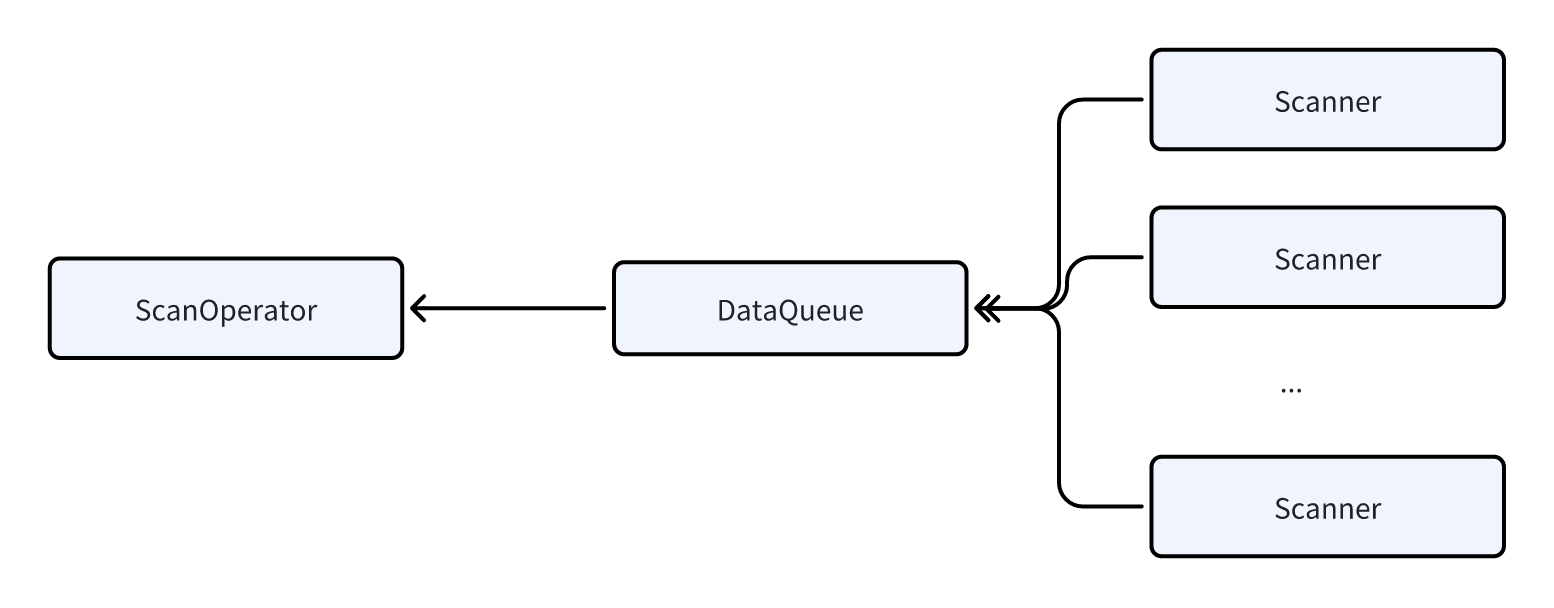
By using parallel scanning technology, we can effectively avoid issues where certain ScanOperators take an excessively long time due to improper bucketing or data skew, which would otherwise slow down the entire query latency.
Local Shuffle
In the Pipeline execution model, Local Shuffle acts as a Pipeline Breaker, a technique that redistributes data locally across different execution tasks. It evenly distributes all the data output by the upstream Pipeline to all the tasks in the downstream Pipeline using methods like HASH or Round Robin. This helps solve the problem of data skew during execution, ensuring that the execution model is no longer limited by data storage or the query plan. Let's now provide an example to illustrate how Local Exchange works.
We will further explain how Local Exchange can prevent data skew using Pipeline-1 from the previous example.
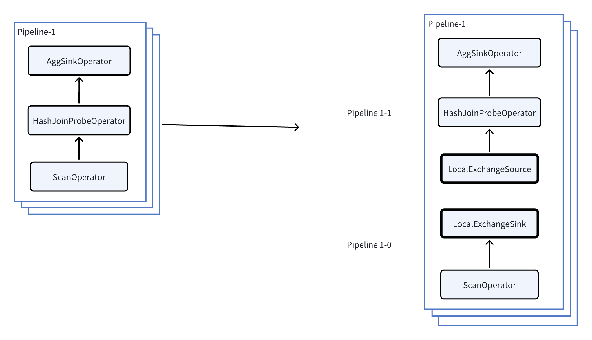
As shown in the figure above, by inserting a Local Exchange in Pipeline-1, we further split Pipeline-1 into Pipeline-1-0 and Pipeline-1-1.
Now, let's assume the current concurrency level is 3 (each Pipeline has 3 tasks), and each task reads one bucket from the storage layer. The number of rows in the three buckets is 1, 1, and 7, respectively. The execution before and after inserting the Local Exchange changes as follows:
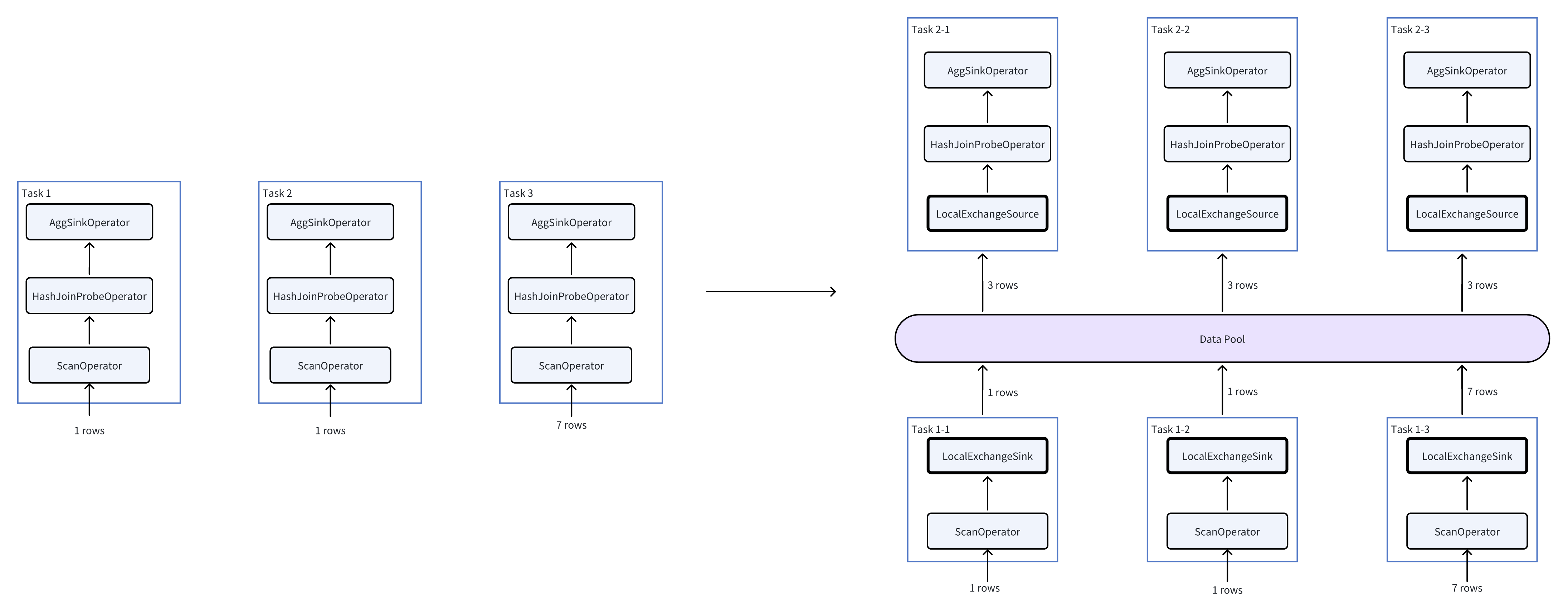
As can be seen from the figure on the right, the amount of data that the HashJoin and Agg operators need to process changes from (1, 1, 7) to (3, 3, 3), thereby avoiding data skew.
Local Shuffle is planned based on a series of rules. For example, when a query involves time-consuming operators like Join, Aggregation, or Window Functions, Local Shuffle is used to minimize data skew as much as possible.
